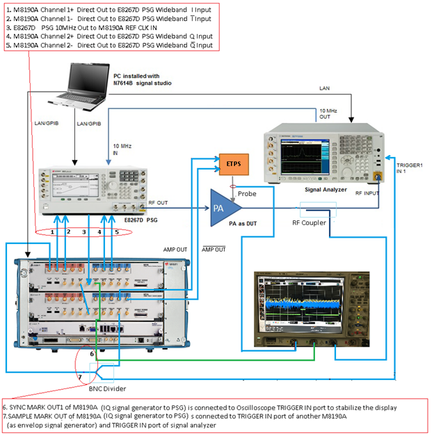
Figure 1 shows the instrument connection of envelope tracking measurement. The figure shows the measurement setup when M8190A AWG is used as envelope signal generator, and M8190A and E8267D PSG is used as RF signal generator.
Figure 1. Envelope tracking measurement setup when M8190A is used as envelope signal generator
In the system connection diagrams above, the dark blue lines are for RF connection; the light blue lines are for reference, trigger, and envelope signal connection; the black lines are for instrument control connection with LAN or GPIB. In envelope tracking test, timing alignment is required between the ETPA Vcc input and the RF input signal.
Follow the procedure below to set up the measurement system:
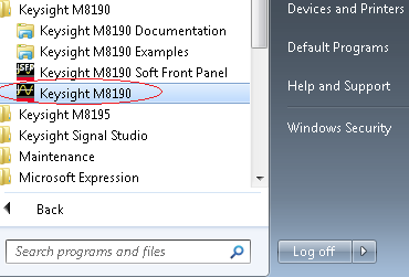
Before performing the envelope tracking and DPD operations using N7614C software, launch the M8190A firmware for both the M8190A AWGs in the AXIe controller. Launch M8190A AWG from the Start menu twice to open the two user interfaces of the M8190A AWG so that we can use the one M8190A AWG as envelope signal generator and one as RF Signal generator.
Check the VISA address of each AWG using the user interface of each AWG.
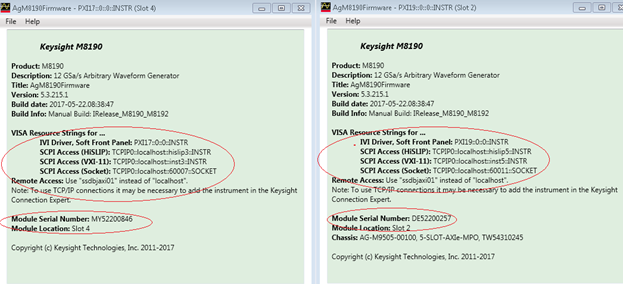
Keysight recommends you to use the 5.3 firmware version of the M8190A AWGs for the ET measurement because it has been verified.
The following mandatory license files are needed for M8190A to be used as an envelope signal generator:
N7614C-AFP
N7614C-EFP
N7614C-FFP
N7614C-HFP
The following hardware options are needed for M8190A to be used as an envelope signal generator:
M8190A-002 – Two channels and two M8190A modules are used
M8190A-14B – Precise Mode is chosen for envelope signal generation
M8190A-AMP – AMP Out differential channels are used to output the envelope signal
M8190A-SEQ – Sequence mode is used to implement the delay adjustment
M8190A-02G – Only needed to upgrade baseband generator memory from 128 MSa to 2 GSa
The table below shows the supported instruments for envelope tracking measurement. For details about the options required for each instrument model, refer to System Requirements.
|
Instrument Type |
Instrument Model Supported |
|---|---|
|
RF Signal Generator |
M8190A AWG |
|
Envelope Signal Generator |
M8190A AWG and PSG |
|
Signal Analyzer |
N9010A EXA N9020A MXA N9030A PXA |
To set up the measurement system, follow the steps below:
Connect IQ baseband signal from M8190A (on RF signal generator path) to the external IQ input port of E8267D PSG:
M8190A Channel 1+ Direct Out to the E8267D PSG Wideband I Input
M8190A Channel 1- Direct Out to the E8267D PSG Wideband I̅ Input
E8267D PSG 10 MHz Out to the REF CLK IN port of M8190A AWG (on RF signal generator path)
M8190A Channel 2+ Direct Out to the E8267D PSG Wideband Q Input
M8190A Channel 2- Direct Out to the E8267D PSG Wideband Q̅ Input
Connect the SYNC MARK OUT 1 of M8190A AWG (on RF signal generator path)to the TRIGGER IN port of the Oscilloscope to stabilize the display.
Connect the SAMPLE MARK OUT of M8190A channel 1 (on RF signal generator path) to the TRIGGER IN port of another M8190A AWG (used as envelope signal generator) and the TRIGGER IN port of signal analyzer.
Connect the REF CLK OUT signal of M8190A AWG (on RF signal generator path) to the REF CLK IN port of another M8190A AWG (used as envelope signal generator)
Connect the 10 MHz signal of signal analyzer to 10 MHz REF IN Port of E8267D PSG.
Connect the RF Out of PSG to the PA IN port
Connect the PA OUT signal to the RF INPUT port of signal analyzer using a BNC cable, and couple part of PA OUT signal to the oscilloscope using a RF coupler.
Connect the AMP OUT signal and the A̅M̅P̅ ̅O̅U̅T̅ signal of the M8190A AWG (used as envelope signal generator) to the input of ETPS, and probe the ETPS OUT signal using a Oscilloscope probe connected to the Oscilloscope for monitoring purpose.